Skip to content

Pulmonx-Zephyr-Clinically-Proven

CT Parameters

The following CT scan radiographic parameters have been optimised in order to provide appropriate input to generate a StratX® Lung Analysis Report.

In order to produce quality output parameters displayed in the StratX Report, it is recommended to adhere as closely as possible to the ideal parameters. If a scan can’t be obtained with the ideal parameters, we have specified acceptable scan parameters on pages 3 and 4. Significant deviation from these parameters may result in reduced accuracy or an inability to analyse the CT scan.

For more specific information related to scan parameters or if your CT scanner manufacturer is not listed below, please contact us directly for support at: stratxEMEAsupport@pulmonx.com

General Information

  1. Ensure all files are in standard DICOM format.

  2. Only SUPINE position chest CT scans with arms positioned above the head are supported. Scans obtained in PRONE position can NOT be analysed.

  3. The CT scans must have a slice thickness of 1.5 mm or less (smaller slices provide more information for fissure completeness) in the axial plane. Reconstruction slice thickness must be greater than or equal to acquisition slice thickness.

  4. The input image should NOT be reconstructed with a slice spacing larger than the slice thickness (slice spacing should be less than or equal to slice thickness, no gaps in the 3D volume are allowed).

  5. The complete lung must be present on the CT scan. If parts of the lung are missing, the output parameters will be compromised.

  6. Only non-contrast TLC (inspiration) scans are accepted for analysis.

  7. Technologist should instruct the patient to take a full inspiration breath and hold. The scan should start once the patient has reached breath hold and relaxed their body.

  8. Ensure the CT scan is not of poor quality (e.g., movement artifacts, artifacts due to metal, high noise levels due to dose level, etc.)

  9. Please ensure the CT scan does NOT suffer from image artifacts such as streak artifacts from implants

  10. Scans taken from CT scanners with less than 16 detector rows are not recommended.

  11. Any series containing less than 120 images will be automatically removed by the system.

  1. Ensure all files are in standard DICOM format.

  2. Only SUPINE position chest CT scans with arms positioned above the head are supported. Scans obtained in PRONE position can NOT be analysed.

  3. The CT scans must have a slice thickness of 1.5 mm or less (smaller slices provide more information for fissure completeness) in the axial plane. Reconstruction slice thickness must be greater than or equal to acquisition slice thickness.

  4. The input image should NOT be reconstructed with a slice spacing larger than the slice thickness (slice spacing should be less than or equal to slice thickness, no gaps in the 3D volume are allowed).

  5. The complete lung must be present on the CT scan. If parts of the lung are missing, the output parameters will be compromised.

  6. Only non-contrast TLC (inspiration) scans are accepted for analysis.

  7. Technologist should instruct the patient to take a full inspiration breath and hold. The scan should start once the patient has reached breath hold and relaxed their body.

  8. Ensure the CT scan is not of poor quality (e.g., movement artifacts, artifacts due to metal, high noise levels due to dose level, etc.).

  9. Please ensure the CT scan does NOT suffer from image artifacts such as streak artifacts from implants.

  10. Scans taken from CT scanners with less than 16 detector rows are not recommended.

  11. Any series containing less than 120 images will be automatically removed by the system.

Ideal Scan Parameters

Following these parameters will achieve the highest quality report possible

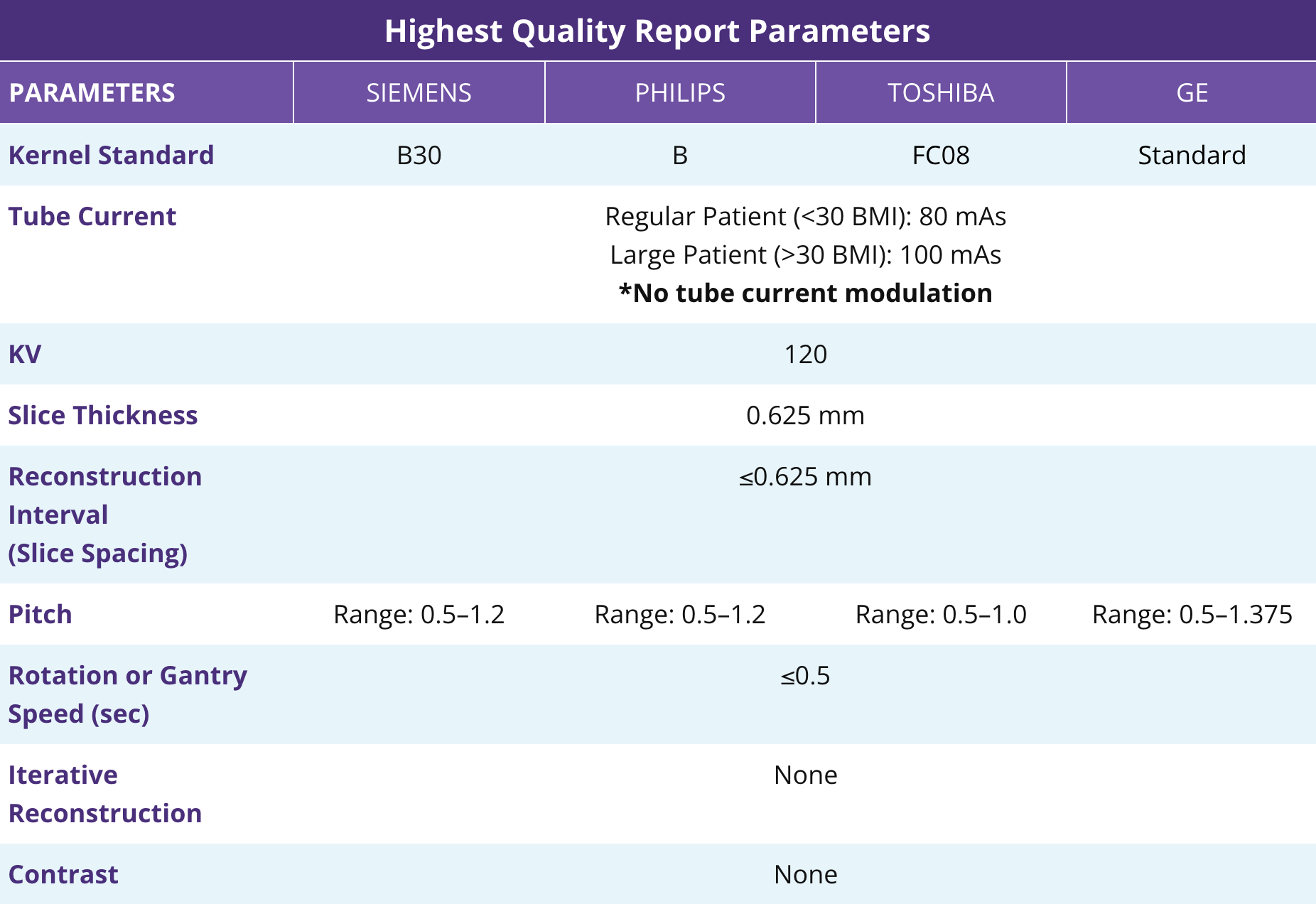
Highest Quality Report Parameters
PARAMETERSSIEMENSPHILIPSTOSHIBAGE
Kernel StandardB30BFC08Standard
Tube CurrentRegular Patient (<30 BMI): 80 mAs
Large Patient (>30 BMI): 100 mAs
*No tube current modulation
KV120
Slice Thickness0.625 mm
Reconstruction Interval
(Slice Spacing)
≤0.625 mm
PitchRange: 0.5–1.2Range: 0.5–1.2Range: 0.5–1.0Range: 0.5–1.375
Rotation or Gantry Speed (sec)≤0.5
Iterative ReconstructionNone
ContrastNone
Highest Quality Report Parameters Table

Acceptable Scan Parameters

CT Scan Parameters WITHOUT Iterative Reconstruction

*No iterative reconstruction preferred

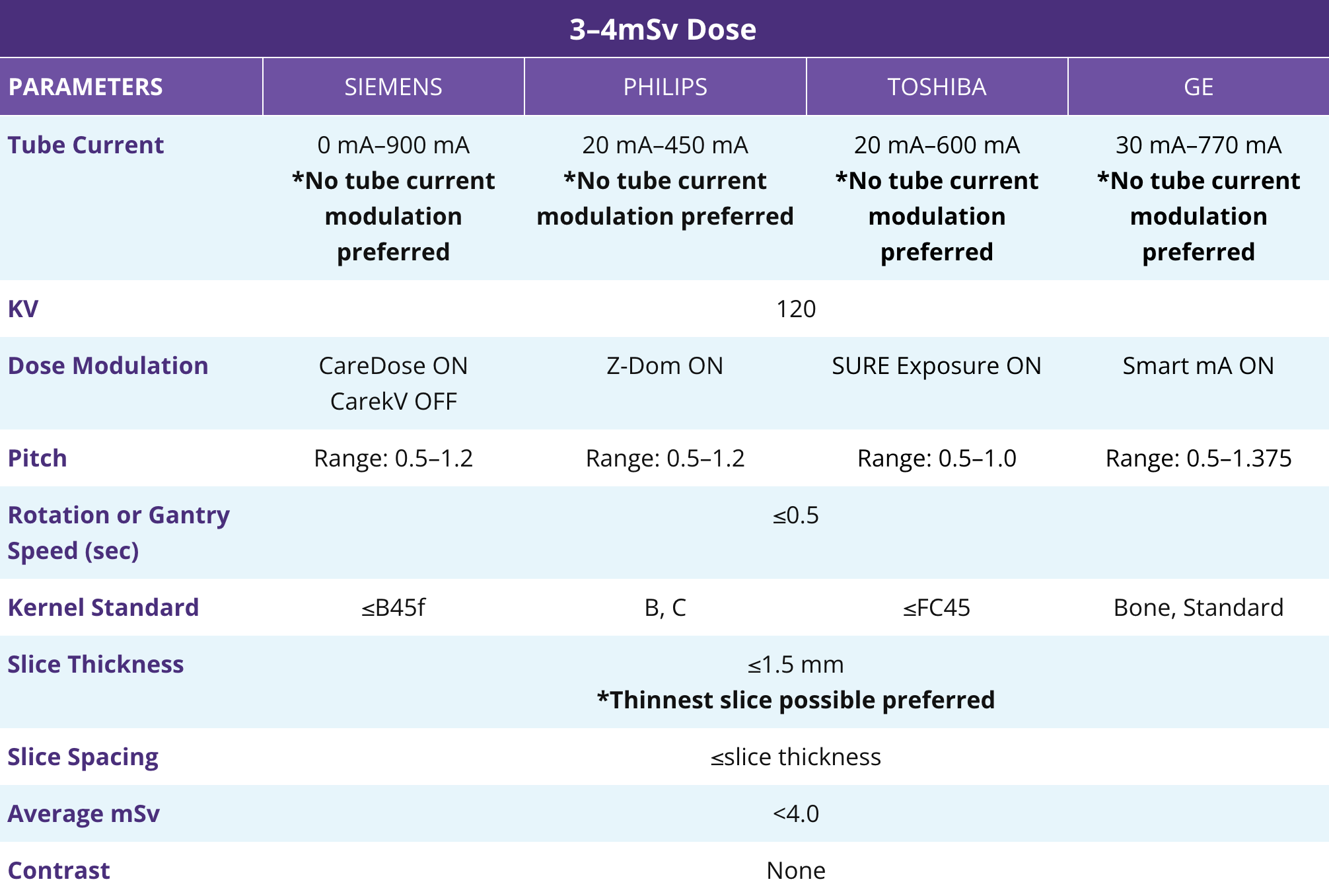
3–4mSv Dose
PARAMETERSSIEMENSPHILIPSTOSHIBAGE
Tube Current0 mA–900 mA
*No tube current
modulation preferred
20 mA–450 mA
*No tube current
modulation preferred
20 mA–600 mA
*No tube current
modulation preferred
30 mA–770 mA
*No tube current
modulation preferred
KV120
Dose ModulationCareDose ON
CarekV OFF
Z-Dom ONSURE Exposure ONSmart mA ON
PitchRange: 0.5–1.2Range: 0.5–1.2Range: 0.5–1.0Range: 0.5–1.375
Rotation or Gantry Speed (sec)≤0.5
Kernel Standard≤B45fB, C≤FC45Bone, Standard
Slice Thickness≤1.5 mm
*Thinnest slice possible preferred
Slice Spacing≤slice thickness
Average mSv<4.0
ContrastNone
3–4mSv Dose Table

Acceptable Scan Parameters

CT Scan Parameters WITH Iterative Reconstruction

*No iterative reconstruction preferred

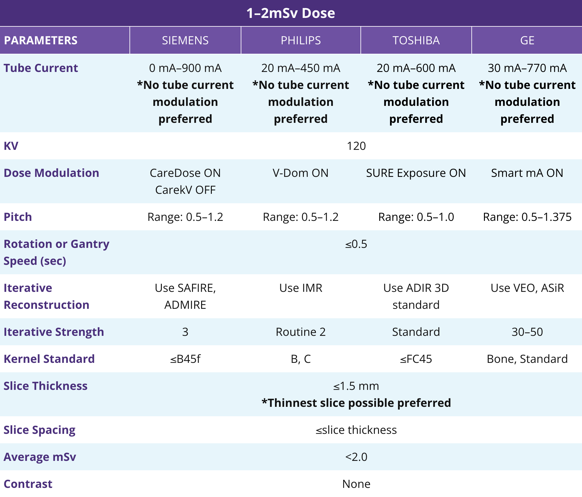
1–2mSv Dose
PARAMETERSSIEMENSPHILIPSTOSHIBAGE
Tube Current0 mA–900 mA
*No tube current
modulation preferred
20 mA–450 mA
*No tube current
modulation preferred
20 mA–600 mA
*No tube current
modulation preferred
30 mA–770 mA
*No tube current
modulation preferred
KV120
Dose ModulationCareDose ON
CarekV OFF
V-Dom ONSURE Exposure ONSmart mA ON
PitchRange: 0.5–1.2Range: 0.5–1.2Range: 0.5–1.0Range: 0.5–1.375
Rotation or Gantry Speed (sec)≤0.5
Iterative ReconstructionUse SAFIRE, ADMIREUse IMRUse ADIR 3D standardUse VEO, ASiR
Iterative Strength3Routine 2Standard30–50
Kernel Standard≤B45fB, C≤FC45Bone, Standard
Slice Thickness≤1.5 mm
*Thinnest slice possible preferred
Slice Spacing≤slice thickness
Average mSv<2.0
ContrastNone
1–2mSv Dose Table

How StratX® Report Results Are Determined

The data presented in the StratX Report is based on Hounsfield units to measure fissure completeness, destruction scores, and lobar volumes. The quality of the uploaded CT images directly influences the Hounsfield unit of measurement. Below are examples of reasons why images will be rejected:

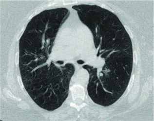
Motion Artifact Scan Rejection

Motion Artifact Image Distortion

Taking a CT scan while a patient is moving distorts the image quality, making it appear blurry or fuzzy. The image distortion directly impacts the accuracy of destruction, fissure, and volume scoring. A StratX Report will not be provided if a motion artifact is detected.
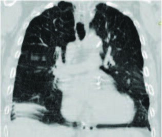
Motion Artifact Scan 1
Motion Artifact Scan 2
Motion Artifact Scan 3

Inadequate Breath-Hold Scan Rejection

Expiratory Scans

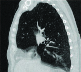
Expiratory scans are noted by the raised diaphragm and lobar compression. Expiratory scans will lead to artificially low destruction scores and inaccurate lobar volumes. A StratX Report will not be provided if an expiratory scan is detected.

Raised Diaphragm
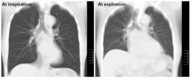
Raised Diaphragm

Contrast Scan Rejection

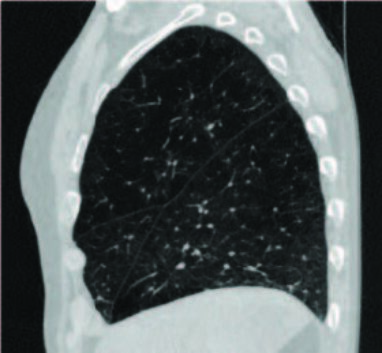
Scans with Contrast

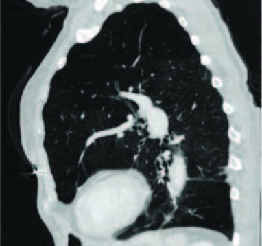
If an image is taken with contrast, the vasculature will appear bright and will permeate into lung tissue resulting in
artificially low destruction scores. A StratX® Report will not be provided if a scan with contrast is detected.
Contrast Scan Rejection 1
Contrast Scan Rejection 2

Incorrect Kernel

Images reconstructed with an incorrect kernel may result in inaccurate destruction scores. In the example below, an incorrect kernel has added noise to the image, resulting in an artificially low destruction score. If an incorrect kernel is detected, a StratX Report will be provided with a warning that the report may be inaccurate.

EMEA-EN-2325-v1